
Murphy’s PowerCore family just got bigger with the new TEC-10. Ready to work out of the box, this controller is the perfect fit for industrial needs. It joins the PowerCore MPC-10 and MPC-20 in the line of powerful, flexible controllers.
Just released, this Turnkey Electronic Controller is designed to plug and play when used with a Murphy Industrial Harness.
The TEC-10 is ideal for applications where cost and quality are key factors along with the need for auto start or auto throttling control. This rugged TEC-10 panel supports J1939 CAN protocols for electronically governed engines as well as I/O for mechanical engines for fault and safety shutdowns.
The new controller boasts three levels of menu security which can be set with the free configuration tool, available for download on our Help Center.
Additional features and benefits of the PowerCore TEC-10 Panel include:
- Viewable in full sunlight with the easy-to-read monochrome LCD
- Supports the latest Tier 4/EuroStage IV and earlier engines
- Intuitive menu guides users through setup
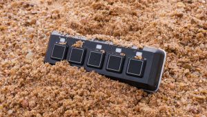
- Tactile feedback buttons allow operators to easily feel when pressed
- Fully sealed to meet IP67 rating
- Carries CE approval
- Includes five language options: English, Spanish, German, French, Italian