Discuss issues and ideas you have to configuring displays with PowerVision
-
CustomFP
- Posts: 41
- Joined: Thu Mar 22, 2012 4:12 pm
Post
by CustomFP » Tue Jun 07, 2016 1:53 am
I am Trying to run an IX3212 using a 3rd party controller while building my own interface.
I am running into a problem where the IX while driving a motor on with gearbox using the H-Bridge driver on HS5 and HS6 outputs not seam to be getting to the full current of 15AMPS before overcurrent disabling.
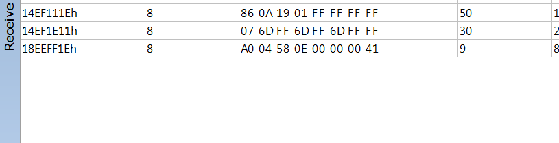
On power up I send the following messages of the CAN header 0x14EF1E11 (The RX message for the IX3212
For 1 second
- IX 07.PNG (6.73 KiB) Viewed 110 times
Then for 1 second
- IX 06.PNG (6.52 KiB) Viewed 110 times
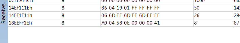
Then step from 1 to 12 on the second byte with this message for 0.2s each step
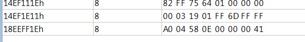
- IX 00 03.PNG (3.98 KiB) Viewed 110 times
After that I cycle between of 04 and 05 on the first byte every 0.1s to command the Driver outputs.
Is this the correct way to configure and command the IX3212. Using the current feedback it looks like the current is only getting to 10Amps before OC disable is triggering.
Also is it possible to use 2 H-Bridge outputs in parallel to drive a motor with double the normal current draw?.
-
stalley
- Enovation Controls Development

- Posts: 618
- Joined: Tue Mar 18, 2014 12:57 pm
Post
by stalley » Tue Jun 07, 2016 8:43 am
Hello CustomFP,
Which Module Type are you using? First Generation or IX3212?
I'll get you some answers to your questions as soon as I can, I'm not very knowledgeable about the PDM, but I can talk to people who are.
This may seem a little crazy, but you should be able to use PowerVision Configuration Studio and a color display to develop a config using the IX3212 PDM Manager application to get the IX3212 to do what you need. Capture the messages that the color display sends to the IX3212. These will be the messages you need from your 3rd party tool.
Thanks!
Sara Talley
Software Engineer
Enovation Controls
-
CustomFP
- Posts: 41
- Joined: Thu Mar 22, 2012 4:12 pm
Post
by CustomFP » Tue Jun 07, 2016 5:33 pm
I am currently using the IX3212 module.
As for using a screen to setup. This is a good idea however I currently do not have a spare screen how difficult would it be to do this experiment on your end?
-
stalley
- Enovation Controls Development
- Posts: 618
- Joined: Tue Mar 18, 2014 12:57 pm
Post
by stalley » Wed Jun 08, 2016 9:16 am
Hello CustomFP,
The question about using two H-Bridge outputs in parallel will not work. The FETs on the IX3212 don't have the capability to work together in parallel to get the higher output.
From the engineer who recently worked on the firmware of the IX3212:
Code: Select all
1.	The PDM command protocol is designed to provide feedback for each command sent to the PDM.  The best way to provision it, would be to send commands to the PDM and verify that the PDM received the commands by inspecting the corresponding Config Feedback, and Feedback commands.
Command with Byte 1=0 (Configuration Motor Model commands) have corresponding Motor Model Handshake responses from the PDM (command 134 decimal or 86 hex).  This allows the controller to verify each channel is properly configured without the need to repeat commands for a period of time.
Configuration for channels 1-6 and 7-12 (commands 6 and 7) have a Corresponding Config Handshake (response 135 (0x86 hex) and 136  (0x87 hex).
This is the best way to ensure the PDM is configured properly.
2.	Once the PDM starts it will send the Handshake commands with the current configuration information.  The display can be sure the PDM is properly programmed by inspecting these values and make any necessary changes.
3.	The PDM will go to sleep if it does not receive any commands sent to it within a period of time.  The PDM will “wake up” when it sees can activity.  Once the PDM is “awake” configuration can be done.
4.   The Command Output Channels message (commands 4 and/or 5) should be transmitted at least every second after the channels have been configured.  Perhaps each message sent every second but with a 500 msec delay between so that a command output channels message gets transmitted every 500 msec.


I might suggest you disable the Motor braking for testing of the operation of the PDM.
You may also try changing the soft start values.  I would suggest you try disabling the softstart delay to see if there is an effect on the operation.

If you could provide the software version of the PDM you have it would help.
The software version of the PDM is provided in response 131 (0x83)  byte 3 and 4 contain the version number as a hex binary number with byte 3 being the least significant byte.
I'm attaching a text file with CAN traffic between a PV780 and an IX3212 that should be configured similar to your description.
Regards,
Sara Talley
Software Engineer
Enovation Controls